CBM
ASCII-X
BASIC
C128
2MHz Border
BASIC 7.80
BASIC 8
CPM
Digimaster 128
Fast Serial for uIEC
Games
Interlace
JiffySoft128
Keyboard Scan
Media Player 128
Orig Interlace
RGBI to S-Video
RGBI to SCART
RGBI to VGA
Ultimate
RGB Conversion
SAM 128
SID Player 128
VDC Interlace
Mp128alpha
N-progs
D64plus
Disk
Escape Codes
Hardware
PCxface
PETSCII
Pet2asc
Futurama
IBM PC-AT
Contact
Games
Glossary
Hall of fame
Hall of shame
Miscellaneous
Privacy policy
Programming
Twisty puzzles
This adapter (developed by me / H2O), gives all 16 colors with a minimal amount of chips (2 or 3). This adapter provides ALL 16 colors:
- the fussy "dark grey"
- the notorious "brown"
- and all other colors with maximum saturation
| How It Works |
To summarize, the 7486 XOR chip, the 74LS138 decoder chip, and about a dozen diodes and resistors are required for the "ultimate" RGBI conversion! Note my circuit only creates an RGBa output (analog RGB), so you still need a VGA adapter to connect to a typical computer monitor. The Ambery VGA adapter is a widely available, moderately priced, adapter which does a good job (once you figure out its various settings). That adapter needs an HD-15 input (hence the output of my adapter), and it also requires +12V to power it. To make things easier for me, and hopefully you, my circuit includes a 7805 to get the +5 volts it needs from the required +12V. If you happen to have a stable +5V power source, then you can use it directly, and omit the 7805 and its associated capacitors.
Note that some VGA adapters will work directly with V-Sync and H-Sync (if so, you might eliminate two XOR gates [I said "might" because of polarity issues]). Some VGA adapters work with either positive or negative composite sync (if so, you can eliminate one XOR gate). The Ambery VGA adapter has inputs for H-Sync and V-Sync, but for some reason they do not work at the frequency provided by the C128/VDC (approximately 15KHz horizontal). Unlike some other adapters, the Ambery VGA adapter only works with negative composite sync, so my circuit uses two XOR gates to generate a composite, negative "Sync" (see bottom middle of the schematic above). In short, if you have a VGA adapter which is more flexible than the Ambery model, you can eliminate one or two XOR gates.
Note the 220 Ohm fixed resistors are a "safety" feature. If somebody turned the variable-resistor(s) to zero, they prevent the circuit from "stressing" the VDC and related circuits of your C128. Previous designs that I published lacked this, although none of my previous testing, over the full-range of variable-resistors, destroyed my C128. However, my testing was for a limited time -- continued use with zero resistance could reduce the life of the VDC or other C128 components! These can be safely (and economically!) eliminated, if you can guarantee the resistance of each R/G/B/I line never drops below 220 Ohms. Similarly, the 82 Ohm resistor is designed to protect both your VDC/C128 and the 74LS138 chip in case the "brown" variable-resistor is turned to zero. Finally, there is no "safety" resistor for the "dark gray" variable-resistor because it feeds into the RGB lines which are already protected.
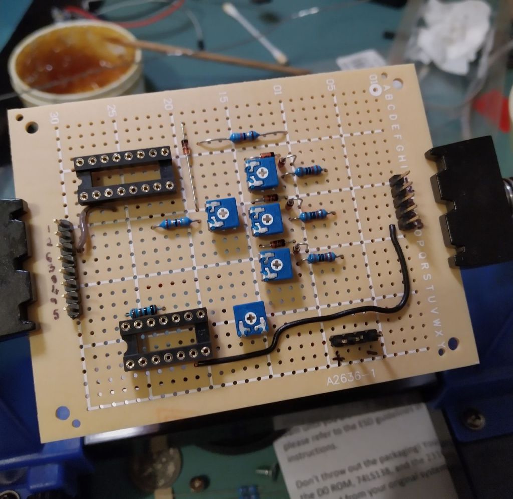
Enough theory! Below is a photo of the circuit board I built. I labeled many of the components in the photo. Just to clarify:
In the photo you can see five (5) variable resistors ("pots"). Three of them are for the basic Red, Green, and Blue (RGB). I used 2K pots to give the "best" (this is an opinion) option between "usable range" and "sensitivity". You could use 1K pots, but then you might have a "range" problem (for example, if the colors are too bright with maximum resistance, there is nothing you can do). Or you could use 3K (or 5K) pots, but then you could see a relatively large change in brightness with a relatively small twist of the pot (a "sensitivity" problem). So I think 2K is ideal, but I have built similar ones with 3K and 5K pots with success.

In case you didn't know, the C128's 80-column output is electronically the same as CGA from an IBM PC. A visitor to my site, Justin D, built my "ultimate" adapter for his CGA card and was kind enough to share some photos with us! The first photo shows my ultimate adapter on a breadboard he assembled (the white block with all the wires) connected to an Ambery adapter (the green board).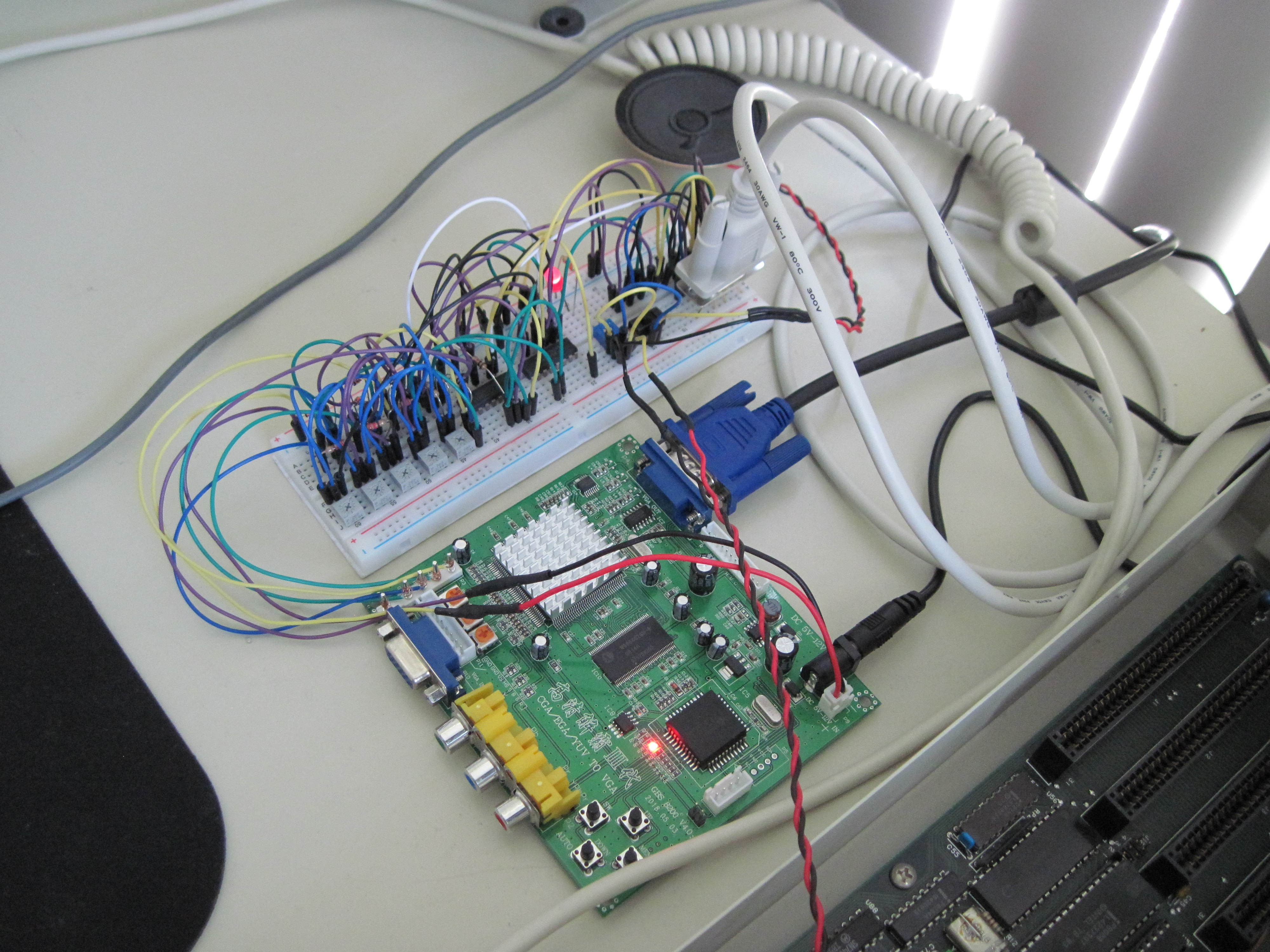
 ,
,
Cheshire Noir reported in late 2020 this works with his C128D. He wrote a detailed blog post you can read. (This guy makes lots of cool stuff, and that blog post features 3 different projects, but the first is about the C128/VGA.) He was kind enough to share some photos with us! The first is a close-up of the "Ultimate" circuit board without any chips inserted into sockets.
 ,
,
 ,
,
 ,
,
© 2017, 2019, 2021 H2Obsession
| Circuit Board |
- "5V Regulator" is the 7805 chip (adapts the Ambery-required 12V to my circuit's needed 5V)
- "3-to-8 Decoder" is the 74LS138 chip (it generates a special signal for "Dark Gray" and "Brown" colors)
- "XOR gates" is the 7486 chip (4 XOR gates = 1 for "Dark Brown" + 2 for Negative Composite Sync + 1 unused)
In the photo you can see five (5) variable resistors ("pots"). Three of them are for the basic Red, Green, and Blue (RGB). I used 2K pots to give the "best" (this is an opinion) option between "usable range" and "sensitivity". You could use 1K pots, but then you might have a "range" problem (for example, if the colors are too bright with maximum resistance, there is nothing you can do). Or you could use 3K (or 5K) pots, but then you could see a relatively large change in brightness with a relatively small twist of the pot (a "sensitivity" problem). So I think 2K is ideal, but I have built similar ones with 3K and 5K pots with success.
Besides the expected "Red", "Green", and "Blue" variable resistors ("pots"), there is also one for "Dark Gray" and another for "Brown". The "Dark Gray" pot allows you to change its color from approximately "Black" to "Light Gray". The "Brown" pot allows you to change its color from "Dark Red" to "Dark Yellow". Also note that I took this photo before I added strain-relief to the input and output cables. You really need to add strain relief to cables going into/out-of a box... otherwise anybody who "pulls" on the cables (by accident or malevolence) will probably rip the wires out of the circuit board... then either the board will silently fail, or perhaps (Murphy's Law!) destroy your computer, monitor, VGA adapter, or power supply!! Finally note I built the case out of aluminum, per my client's request. Not only does it give a shiny appearance and a very solid feel, but it should also shield the circuit from outside interference (and minimize "broadcast" interference). However, I have built similar circuits using a plastic case with good results (plastic is cheaper and slightly easier to sculpt).
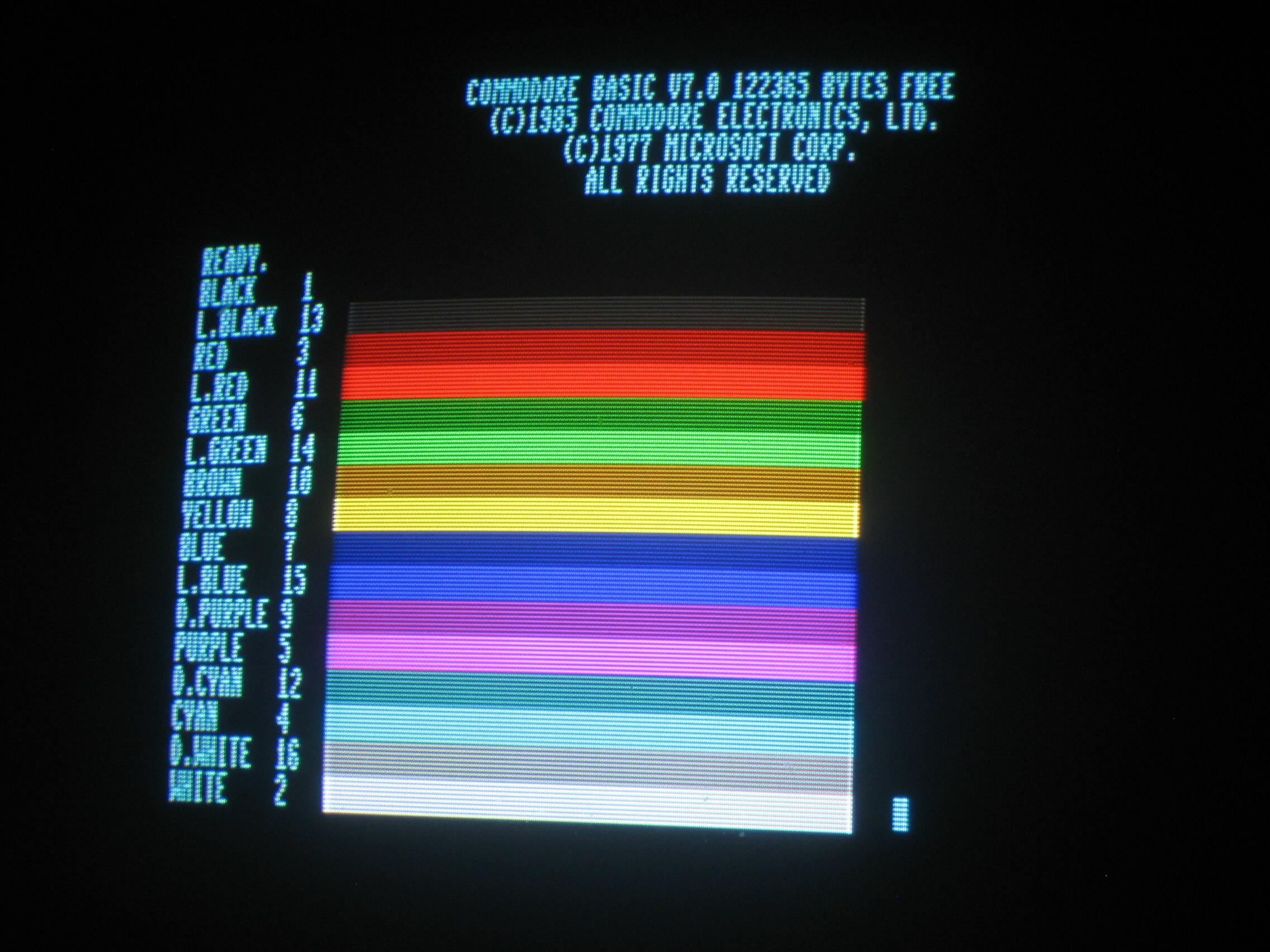
"The proof is in the pudding" is the saying which comes to my mind at this point. Below is a photo of a VGA monitor using my "Ultimate" RGBI converter with the Ambery VGA adapter. The photo shows all 16 colors to be very distinct. The colors are all "crisp" (no desaturation). In particular, "Brown" is really brown (and not "dark yellow"), and "Dark Gray" is labeled as "L[ight] Black" (which is correct from "a certain point of view" to quote Obi-Wan Kenobi). This photo is from the C128 operating in standard (non-interlace) mode. I also tested it with interlaced-text mode and got excellent results (I'll see if I can find a photo of that for you). The only thing I didn't test is all the non-standard video modes that the VDC of the C128 can generate.... because the Ambery VGA converter works differently with different horizontal frequencies (no official documentation on limits), my solution (or rather the Ambery converter) might fail with custom graphic modes of the C128. In other words, I haven't tested everything (could anyone?), but what I have tested works superb... which is yet another reason I call this circuit the Ultimate.
| Screen Shot |
| CGA to VGA |
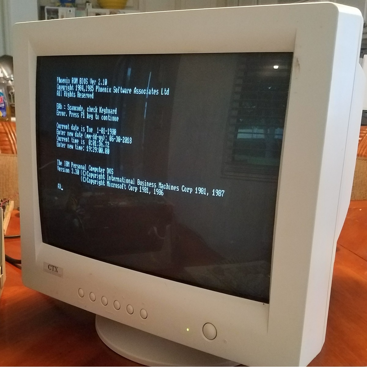
His second photo shows a close-up of a monochrome text screen. If look close, you should see the text has some "digitization errors". For example, on the line that reads "All Rights Reserved", look at the two L's in the word "All"; you should see these two "identical" letters appear different (one looks a bit wider than the other to me). This is an issue with the Ambery VGA converter (not my RGBI Ultimate adapter).
If you play with the Ambery settings you can minimize this distortion, but the Ambery's settings are global. For example, if you tweak the settings for standard C128 text mode (to reduce/eliminate errors) but then switch to Interlace Text or Bitmap mode then "errors" may appear again. Because of "digitization errors", I do not use the Ambery adapter (or any VGA adapter)... I prefer to convert C128 80-column to S-Video and connect it to a TV (instead of a VGA monitor). Most modern TVs (in the USA as of year ~2010) do not have an S-Video input which means you might also need something like an S-Video to Component adapter...
Justin's third photo shows a VGA color display, his IBM PC, my RGBI adapter, and the Ambery VGA converter. The video display looks pretty good to me, although most people (I presume) would like a nice case to hold the Ultimate and Ambery adapters.
, Here is a big THANK YOU to Justin D for sharing... I never thought about using my adapter with an IBM PC, but he shows that it works!
| More Real Examples |
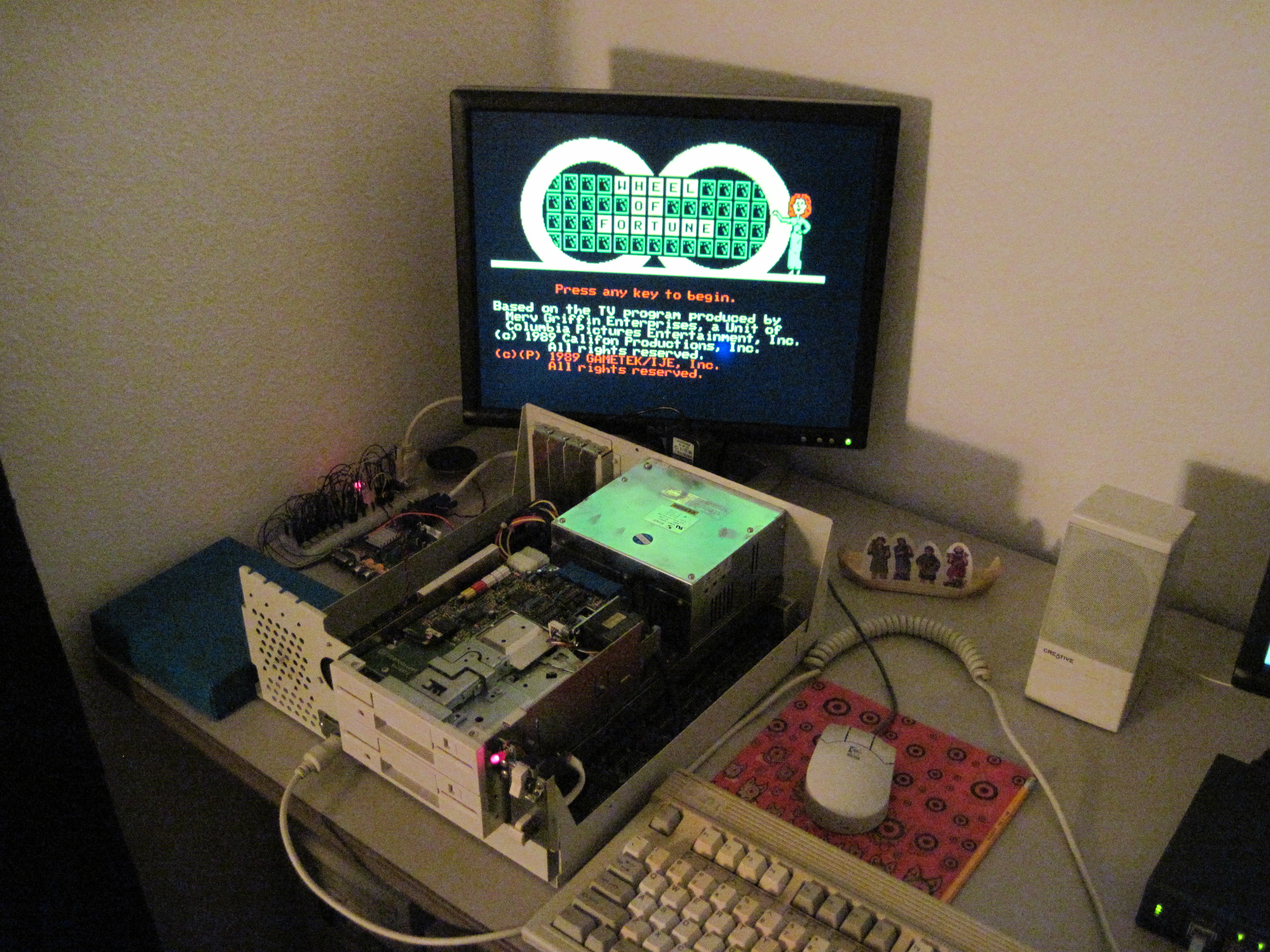
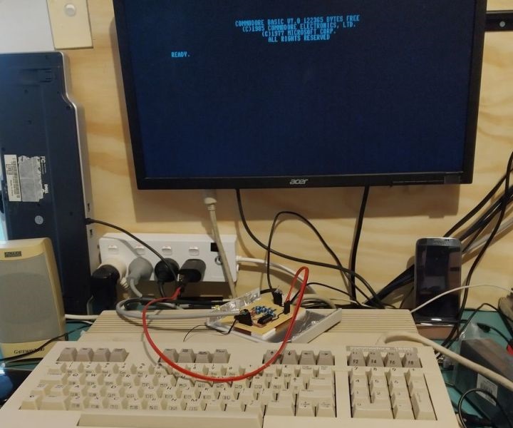
, His next photo shows only the "Ultimate" adapter connected directly to his VGA monitor. His monitor shows a nice, clean, text image. Unfortunately the monitor only shows standard text in a single color. However, his photo gives you a scale of how big/small the "Ultimate" adapter is, relative to a stock Commodore 128.
WARNING: not all (perhaps a minority of) modern monitors will DIRECTLY produce a usable display with my Ultimate adapter, but I hope his photo "proves" it can work. (In case you doubted my previous words, math or photos!) If your monitor does NOT like your C128 / my Ultimate adapter, then keep reading...
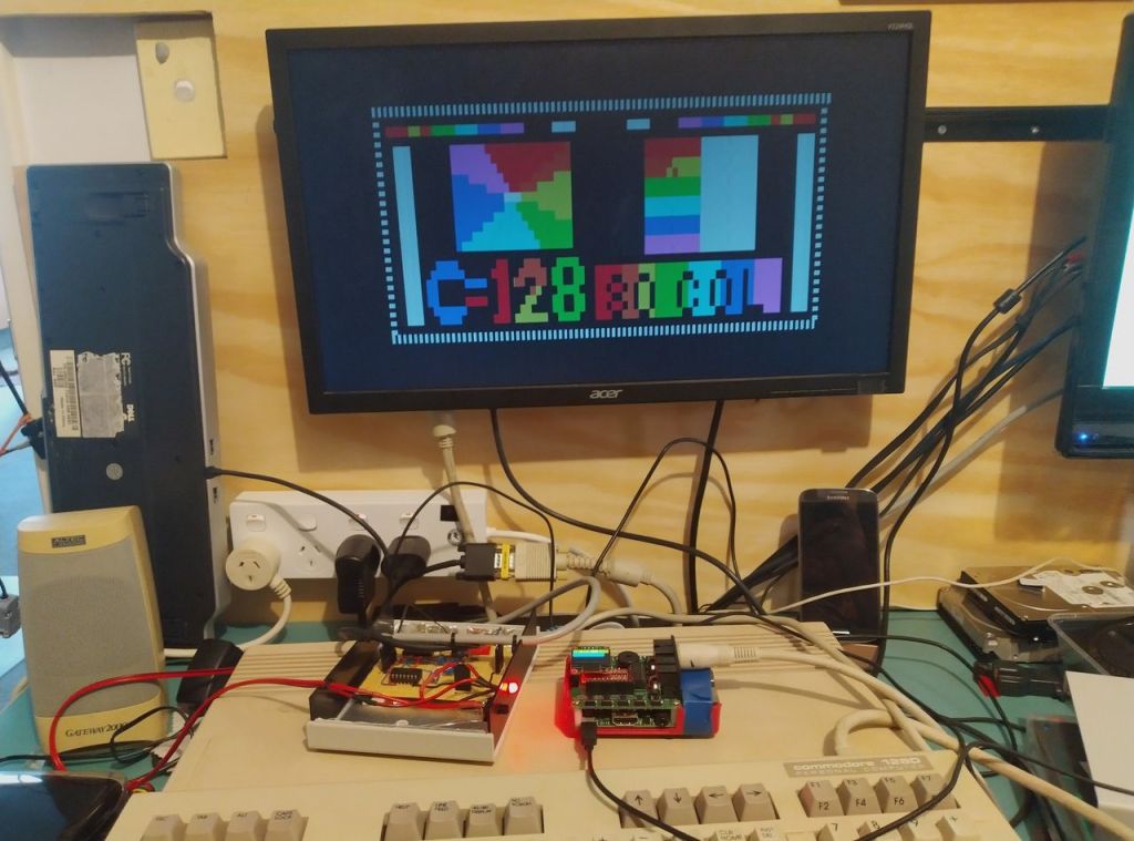
, The final photo by C.Noir shows his build of my Ultimate adapter connected to the commercially available Gonbes 8200 CGA->VGA adapter. This other device basically acts like a 'line doubler' converting C128 (CGA) output frequency of 15.75 KHz into "standard" VGA line frequency of 31.5 KHz. His photo shows the two video devices connected together, to his C128 and his VGA monitor. The nice thing about this photo is that it shows all 16 colors (although still text mode). The colors look good (my biased opinion) but the monitor is only showing text... you have to imagine bitmap graphics.
, Now that I look closely at C.Noir's color display, there is something obviously wrong. There should be 16 colors, but I only see 9. Nine? What is happening here? I don't know... it is almost like the Intensity line is "broken" -- a generic CGA display has 8 colors. His photo shows 9. The extra one? Well that is Orange (dark yellow). My orange circuit relies on the Intensity line, so his build is not completely broken (based on photo). Yet there should be a clear difference between pairs like green / light green which are missing. Maybe there is a slight difference in real-life not captured by the photo? But my testing showed very clear differences... more investigation is needed!!
© 2017, 2019, 2021 H2Obsession
Images "JustinD/leadingedge37", "JustinD/dos_monitor", and "JustinD/lab2" © 2018 Justin D. Used with permission.
Images "CNoir/Board", "CNoir/WorkOnC128r", and "CNoir/Colors" © 2020 Chesire Noir. Used with permission.